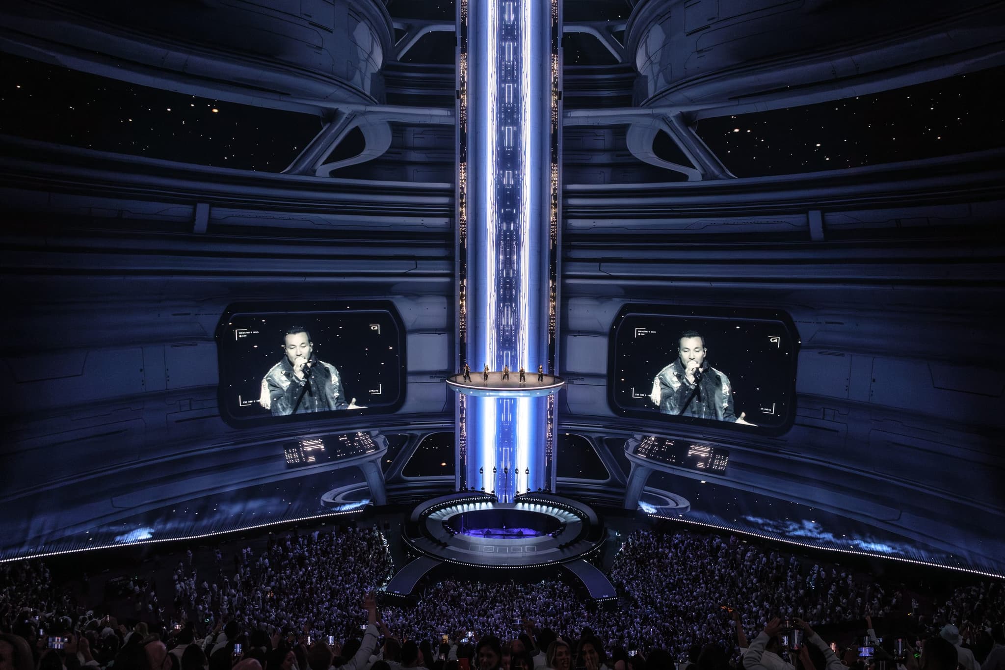
A Backstreet Boys production needed a flying stage element for their show. The element measured 25 feet by 45 feet and weighed just under 13,000 pounds. It had to stay wireless. It had to control lighting, special effects, and deliver audio to performers mid-air. And it had to work flawlessly in front of 18,000 people every night.
The venue made standard wireless solutions impossible. LED walls everywhere. Thousands of phones competing for the same frequencies. Every standard approach failed before doors even opened.
Technically Creative built a system that never dropped. Not once. Zero timing failures across 50+ shows.
The Challenge
Flying stage elements create a simple problem: you need wireless power and wireless control. Cables don't work when things are moving through the air.
But this venue had a bigger problem. The wireless spectrum was already full before the first audience member walked in. LED walls emit interference. Venue infrastructure occupies frequencies. Then add 18,000 people with phones, and the wireless environment becomes hostile.
The flying stage element needed to do three things without failure: - Control special effects and lighting cues in sync with the show - Deliver audio to performers through in-ear monitors - Run for extended periods without visible power issues
A single dropout would be visible. Lighting cues would miss. Effects would fire at the wrong time. Performers would lose audio. In a high-stakes live environment, there's no second take.
The Solution
Wireless communication that worked in a saturated environment. A dedicated wireless link operating on frequencies that weren't competing with venue infrastructure or audience devices carried lighting control, video feeds, and monitoring data. Timecode ran on its own three-layer redundancy architecture with automatic failover.
Power distribution built for reliability and speed. Instead of custom fabrication, we adapted consumer battery systems that were already certified for venue use. The batteries ran the pod while airborne, then automatically switched to charging when grounded. The entire power system was built in four days.
Real-time monitoring that made problems visible before they became failures. A unified dashboard pulled power status, network health, and visual confirmation into a single operator view. If something started degrading, the system could shed non-critical loads remotely to protect essential functions like performer audio.
Why This Approach Works
The system eliminated single points of failure. Wireless communication had a backup path, if the primary link dropped, the backup engaged automatically. No one had to touch a button. Power capacity looked like overkill but enabled operational flexibility: the element could stay live for hours or days during programming. Monitoring turned invisible system status into actionable data.
The timeline was tight. Four days from concept to completion. Pre-certified components eliminated approval delays. Modular design meant capacity could expand without starting over.
60 GHz Millimeter-Wave: Stop Competing Entirely
We needed a communication path that wouldn't compete with saturated bands. The answer was to stop competing entirely.
60 GHz millimeter-wave operates outside the congested spectrum, a point-to-point link using a Ubiquiti Wave AP to Wave Nano pair. This band offers 9–14 GHz of bandwidth in largely uncongested space. The high attenuation that normally limits range becomes an asset: signals drop to noise level within 2.5 km, preventing interference with other systems.
The link carried all IP traffic to the flying stage element: - sACN for lighting control - Streaming video in and out - Network communications via VLANs - Monitoring data
Timecode: Three Layers, Zero Excuses
Timecode ran on three layers: sACN as primary, wireless distribution as the first fallback, and a dedicated direct-RF path as the second. If sACN failed, the network degraded, or the wireless path dropped, an automatic RF switch engaged and sent timecode directly to the receiving unit, removing all IP stack dependency. Network failure did not equal timing failure.
This wasn't redundancy theater. When timecode fails, lighting cues miss their marks. Effects triggers fire at the wrong moment. The element's lighting stays active from doors onwards, even when nested in the stage. A timecode failure means visible degradation in front of thousands of people.
Power: Consumer Systems Beat Custom
The flying stage element needed power for lighting, lasers, network hardware, video systems, and effects triggers. All wireless. All airborne. Most teams would build custom. We adapted consumer battery systems instead.
Three EcoFlow DELTA Pro Ultra inverters, each paired with dual batteries, all feeding into their Smart Panel. The system was UL listed, venues don't approve non-certified power systems, and the timeline was four days. The Smart Panel handled switching automatically: element in the air, runs on batteries; element touches down, switches to shore power and charges at 50 amps.
Distribution ran multiple True1 circuits via Socapex breakouts, individual 20A breakers across bus bars, and L6-20 outlets for 240V laser loads, all housed in a custom 3/4-inch Baltic birch caddy with a 20U rack section for networking and control hardware.
UL listing delivered immediate venue approval. Modular design allowed capacity expansion without starting over. 50-amp charging meant fast turnaround between shows. When the timeline is measured in days, not weeks, this approach wins.
Monitoring: Nothing Is Blind
A single dashboard pulled data from three sources: the EcoFlow API for power metrics, the UISP portal for network health, and Ubiquiti cameras for visual confirmation of lighting node status.
The operations layer showed real-time state of charge, watts in and out, remaining runtime, a color-coded circuit heatmap, leg balance, and an alert banner, overload warnings at 80% load, pulsing red at 90%, battery alerts at 20% and 10%. The engineering layer tracked state of health, cycle counts, cell imbalance in millivolts, thermal spread, and relay wear: what breaks, before it breaks.
If power dropped mid-show, the operator could remotely kill non-critical loads. Shed the lighting. Drop the effects. Keep the performers' in-ears alive.
The Failure Patterns This Avoided
Most teams would have gone custom, and lost the monitoring infrastructure entirely. They would have underestimated power capacity; what looks like overkill enables extended programming time. They would have skipped the timecode redundancy because it feels like unnecessary complexity, until a few seconds of dropout creates visible failure in front of thousands of people.
Design Principles
Each decision addressed a specific failure mode: - RF saturation eliminated standard wireless → 60 GHz millimeter-wave bypassed congested spectrum - Custom power distribution would miss the deadline → adapted consumer battery systems with UL listing and fast charging - Invisible system status creates operational blindness → unified monitoring dashboard with real-time alerts - Single-path timecode creates synchronization vulnerability → three-layer architecture with automatic failover
The element flew. The effects fired. The performers heard themselves. The system never dropped.